Construction
Before you start
I'm really glad that you are interested in my board. You can contact me for ordering a board, or use the gerber files in
the download section to order one at your favorite pcb manufacturer. However, before you begin you must realize that:
- you must have good soldering skills and tools
- there are several components that need to be programmed, like an eprom, Microchip PIC18F4525 and some Xilinx CPLD and FPGA devices
- general knowledge of the Acorn Atom or 8-bit microcomputers in general is a must
- trouble-shooting might be hard and difficult
Design considerations
My first intention was to build an Atom main board that would replace the original Atom main board. After a lot of research and discussions I made another decision. The board is only half size of the original one. The keyboard is not part of the new main board. This choice was made because of three reasons:
- Not everybody might have a spare Atom keyboard and it's hard to get the keyboard off an old main board
- By separating main board and the keyboard you can also attach another keyboard
- Integrating a keyboard makes the pcb twice as large, and also double the costs of the pcb
The memory map is based on the defacto standard that we used back in the 80's in the Dutch Atom User Group. This memory map provides 32 kB of ram for your basic or machine code programs, up to eight banks of 4 kB ram for utility roms at #Axxx and it is possible to replace the eprom (#C000-#FFFF) by ram for loading another operating system rom like your own creation or BBC Basic. The memory area at #4000-#7FFF is implemented as four banks of 16 kB each, providing 64 kB ram (this is windowed within the 32 kB program memory space).
The I/O space is much better used. This makes more room for additional I/O. All addressing is handled by two CPLD's so you can create your own memory map without cutting tracks.
Hardware modifications
For all boards the polarity of capacitor C37 is in the wrong way around. The + lead should go to ground and the - lead goes to pin 6 of the MAX232! The symbol on the silk screen is wrong.
Unfortunately I made a few mistakes while designing this new main board. These mistakes will be corrected before I'll order the
next batch of pcb's. But if you have a board with date "2014-10-04" then you'll have to pay attention to these issues:
- All electrolytic capacitors marked with capapol are 100µF
- You can skip the resistors R35, R36 and R37. They were intended to prevent the Atom hanging if there is no 6522 VIA installed. However, these resistors should connect D1, D2 and D3 to ground but that went wrong in this design. You can still use the Atom without a 6522, but then you'll have to mount these three resistors via a separate ic-socket in the 6522's socket.
- The inner pins 32 of PL6/7 (here X1001 and X1002) are not connected. To be compatible with the original Atom, you can put a big drop of tin on these pins.
- The 18F4525 is powered at 3.3V. First of all, you'll need a 18FL4525 for that voltage but that might also affect the performance of the PIC. It's better to connect it to 5V. This can be done easily by drilling a bigger hole in the via (not the 6522!) and then connect pin 32 of the PIC to a 5V line. You can see this at the images below.
- Another mistake is that at the PIC the pins 23 and 24 are swapped. This could be solved in the PIC software but that would
make it incompatible with all the other existing AtoMMC2 interfaces. The neatest way to solve this is to bend out pin 7 of the
SD-card holder. Take care, because pin 7 is the 8th pin from the right if you face the slot towards yourself. Look at
this picture for details.) Solder a short piece of wire to it and isolate it. Connect this piece of wire to the hole of R29 that is the
closest to R34. Do this at the
component side. Now you have connected pin 24 of the PIC to the right connector of the SD-card holder. Then solder R29
(1.8 kΩ) to a piece of wire. Solder the other side of the resistor to the other (still free) hole of R29 on the pcb (that's
the hole nearest at the SD-card holder). The other end of the wire goes to pin 23 of the PIC.


- I strongly advise to use a 1x8 header connector as P1. This is the connector where you connect the GODIL video and audio signals to the main board. You can connect these wires directly to the main board, but if they break you have a challenge to restore them.
- If you intend to use the internal speaker then you have to connect pin 2 and pin 4 of the LM386 with each other. This fix provides the ground terminal (pin 4) to be connected to the ground signal. The LM386 works much better this way.
Soldering components
For the best result you should add the components from lowest to highest footprint. So start with the resistors, then add the sockets for the ic's. Continue with the small capacitors and add the electrolytic capacitors as last ones. The part list and electrical diagram are displayed on the documentation page.
Attention: do not mount R35, R36, R37 and R29! Look at 'Hardware modifications' for an explanation.
The board is of good quality. Soldering the components is easy and nice. But take care that you each component have to solder only once. Removing a component is difficult and the hole might be too small for replacing the component. This goes especially for the VGA connectors.
Attention: do not fit the ic's in their sockets yet. First we'll program the CPLD's and FPGA.
After you have programmed the CPLD's and FPGA you can fit all the ic's in their sockets. All ic's have the same orientation except the two CPLD's. If you look at the board with "Dutch Acorn Atom" text in the lower right corner then all ic's have pin 1 to the upper side of the board. A very detailed picture hides behind this link. Thank you Multiwizard for this photo :-)Programming the components
For programming the CPLD's you can build a simple programming device that connects to your pc's parallel printer port. You can
download the software for this at the Xilinx website. Look for ISE 10.3 because that is the last version that supports the
parallel port programmers. This is the schematic diagram of the programmer:
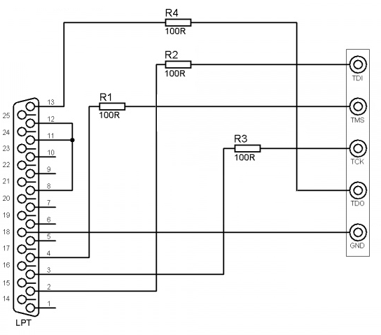
The CPLD's can be programmed in-circuit. Actually, I strongly advise to place them in their socket and never remove them unless they are faulty. The sockets are very fragile and break easily when you use a little too much force when removing the ic's. The memory decoder (XC9572XL) goes into socket U5 (lower left corner). The io decoder (XL9536XL) goes into the top-middle socket (U6). Take care of their orientation. U5 has pin 1 at the right side; U6 has pin 1 to the left side. If you're in the slightest bit of doubt, double check and compare to the great example. You can see the nodges that indicate pin 1.
For programming the CPLD's, download the files from our download page. You only need the .jed files from the archives. Programming the CPLD's is quite straight forward: start iMPACT, create a new project, auto configure the cable, select a device (i.e. the jedec file you want to program and start programming.
Programming the FPGA on the Godil is a bit more complicated. Start with downloading the .bit file from our download page. Then continue with the instructions at Github. I never tested the CPLD programmer with the Godil because the connector pitch is different.
Once you have programmed your Xilinx logic, you can fit all the other ic's. If you ever need to reprogram one of them, you can do this in circuit without removing any component. Of course the Atom will stop working and the screen may go black during the programming. This is a normal behavior. Please save all data and remove the SD-card (better be safe than sorry). After reprogramming a power cycle is recommended.
The next one to program is your 27256 eprom. This file is also at our download page. Use your favorite eprom programmer for this job. There's no simple design that you can build in 10-15 minutes; if you don't have an eprom programmer this will be a hard step.
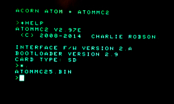
The same goes for programming the PIC. You also need a special programmer for that one. The .hex file is on our download page. On the internet are several simple programmers that might do the job for you. I use the one listed at Voti. It is simple and cheap but it does the job wel. Future firmware updates can be done by placing the new firmware file (atommc25.bin) in the root of a newly formatted card. Enter that card in the SD slot and press break. The red led will flash during updating the firmware and the Atom screen only shows "ACORN ATOM" without a prompt. After the firmware is updated, the normal Atom prompt appears.
I can imagine that you don't want to buy the programming hardware for just a one time use. If you need help, ask on the StarDot forum if there is anybody in your neighborhood to help you.
Connecting the keyboard
I used my old worn out Atom's keyboard for my new Atom. For that purpose I sew my Atom in two pieces
(Splitting the Atom ;-) and
connected the keyboard to my new Atom. I used a 26p flat cable to connect it to the keyboard connector. This is the connection
schema:

In the future we (forum members) might develop an alternative keyboard interface such as an adapter for a PS/2 keyboard. There is a +5V terminal on the connector that can feed the interface.
Testing your Atom
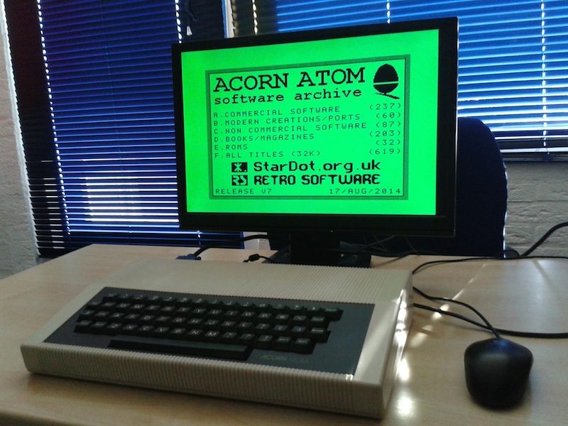
If you have done a nice job of soldering, do a visible check for short circuits. Also double check if there are no components installed in the wrong position (in many cases you will swap Vcc and Gnd with kills the component). If you are ready, connect a VGA monitor to the main board and power the system on. If every thing went well, you'll see the text ACORN ATOM at your screen. If every thing is better then well, you'll also see + ATOMMC2 and a prompt.
Now there are several people who have build this new Atom. And every one of it didn't work quite well the first time. But we
learn from mistakes, don't we? In the following list you can see some issues that we found and worked out. Luckily most of them
are "user errors" :-)
Keyboard doesn't work
This turned out to be a documentation error. One of the wires was not correctly documentated on the keyboard numbering picture. I have corrected this error so now it's correct. When your keyboard doesn't work there are two things to test:- If there appears a character on the screen when you press the REPT-key you probably have a wiring error. The Atom sees a pressed key and waits until this is released.
- Disconnect the connector on the main board and connect the upper row (at the resistor side) to GND. This should give characters on the screen. If not, check your 7445 and 8255.
Reading from the SD-Card gives "Not ready" errors.
Check if the resistors R26, R32, R30, R29, R31 and R38 (near the SD-card socket) are correctly fitted and have the right value. One of the builders used resisters of 18kΩ instead of 1.8kΩ. These resistors are level-shifters that convert the 5V outputs of the PIC to 3.3V input levels for your SD-Card.Memory issues
One of the builders had "raid-1" memory. Every content at #2xxx also appeared at #3xxx, #4xxx also at #5xxx etc. In this case the copper track RA12 between the CPLD and the ram memory was broken. Good memory tests are using option 'F' of the Atom Archive menu and the game Chucky Egg. They probably crash when your memory is not ok.
Putting it together

As you can see in the video where I splitted the Atom, I leave a strip of about 1 inch (2.5 cm) from the keyboard edge. This gives a perfect placeholder to mount the new main board. By simply connecting it with two bolts and nuts you can make a solid connection. I enlarged the two holes where the two case-screws pass through so the fit over the shaft of the bottom half. This compensates the increased thickness of the overlapping pcb's.
The bottom half of the case needs some cutting too. Especially where the VGA connector is but also between the old printer
port and the expansion connector. With a little sanding and scraping, pushing and pulling it finally fits in the original case.
Your best Atom ever....