YARRB
Before you start
I'm really glad that you are interested in my board. You can contact me for ordering a board, or use the gerber files in
the download section to order one at your favorite pcb manufacturer. However, before you begin you must realize that:
- you must have good soldering skills and tools
- there are several components that need to be programmed, like an (e)eprom and a Xilinx CPLD
- general knowledge of the Acorn Atom or 8-bit microcomputers in general is a must
- trouble-shooting might be hard and difficult
Design considerations
I wanted to create an Atom Ram/Rom Board that provides the same flexible memory map like my Atom 2015 and leave the connectors
PL6/7 free for other applications. In the past we had a "combikaart" that gave us some banks at #Axxx and 32k of RAM in the
lower address space. But building a "combikaart" is a lot of work, it needs loads of mods in the Atom and then ... you only
have a little bit of extra memory.
So that's why I decided to create another Ram/Rom board that fits into the 6502 socket of the Atom. In fact you can look at it
as a universal Ram/Rom board because it might work in other 6502 based computers as well. You only have to re-write the code
for the CPLD to make it work in another machine.
I first wanted to use a 27128 eprom to boot the Atom, load the desired firmware into RAM and run from that configuration, just
like the Atom 2015. However, people on StarDot convinced me to use a 128k EEPROM and make it compatible to the existing Ram/Rom
board. So I did. There's still the option to use an eprom with a small modification of the board. BTW, I didn't buy such Ram/Rom
board because it doesn't support loading the operating system into RAM.
Hardware modifications
The YARRB has some options that can be set up with jumpers, there are also a few hardware mods to allow some other components.
- Using a R6502 or compatible CPU: close JP4 on pins 1 and 2 and close JP5.
- Using a WD65C02: close JP4 on pins 2 and 3. Leave JP5 open. Install R1 and R2 (both 4k7)
- CPLD register select: by default the CPLD will use two registers, one at #BFFE and one at #BFFF. For this configuration the jumper JP3 should be installed on pins 1 and 2. If you want two additional registers, install this jumper on pins 2 and 3 and install P6 (that feeds A1 into the CPLD pin 44).
- P6 can also be used to control a Vpp line to the EEPROM, close P4.
- To prevent writing to the EEPROM you can remove P5. But then you have to add a 4k7 resistor between the pins 31 and 32 of the EEPROM socket otherwise the EEPROM might not be readable (this is a design flaw in the board, this resistor should have been there).
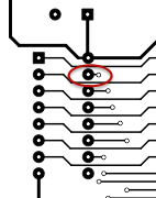 By design, the selection for #BFFE/#BFFF is supported by a 74LS133.
You can also use a 74LS30 (which will be removed from the Atom
when this board is installed) by cutting A13 next to pin 15 by drilling the via next to the pin and connect pin 16 to pin 15 with a
big drop of tin. The CPLD should be programmed to use A15...A8 for the upper address byte selection. This way you can also move the CPLD
registers to another address for use in another comuter system. As long as the lower address byte can be #FE/#FF you can address it anywhere
in the memory map.
By design, the selection for #BFFE/#BFFF is supported by a 74LS133.
You can also use a 74LS30 (which will be removed from the Atom
when this board is installed) by cutting A13 next to pin 15 by drilling the via next to the pin and connect pin 16 to pin 15 with a
big drop of tin. The CPLD should be programmed to use A15...A8 for the upper address byte selection. This way you can also move the CPLD
registers to another address for use in another comuter system. As long as the lower address byte can be #FE/#FF you can address it anywhere
in the memory map.
- You can use a 27256 (or similar) eprom by connecting pin 32 to pin 30 of the rom socket. With a bit of programming you can use two memory banks of 16k for the Atom firmware area, for example AtoMMC in one bank and AtomDOS in the other. I did this in a 32k/64k version of Yarrb with a XC9536XL CPLD in http://stardot.org.uk/forums/viewtopic.php?f=44&t=11373&p=149332#p148604.
Parts list
(Conrad part no 719325-89, Farnell part no 1022217)
Please note that you can also use equivalent components for the semiconductors.
Soldering components
A few compontents have to be mounted on the solder side. This is especially true for P2 and P3 (the headers that go into the Atom's 6502 socket) and for C6 and C8. C7 can also be mounted on the solder side but depending on it dimensions it might also fit on the component side.
For the best result you should add the components from lowest to highest footprint. So start with the resistors, then add the sockets for the ic's. Continue with the small capacitors and add the electrolytic capacitors as last ones.
Attention: first mount the components at the solder side before mounting the sockets for U3 and U4!

The board is of good quality. Soldering the components is easy and nice. But take care that you each component have to solder only once. Removing a component is difficult and the hole might be too small for replacing the component.

Programming the components
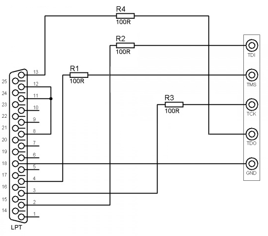
For programming the CPLD you can build a simple programming device that connects to your pc's parallel printer port. You can
download the software for this at the Xilinx website. Look for ISE 10.3 because that is the last version that supports the
parallel port programmers. This is the schematic diagram of the programmer:
The CPLD can be programmed in-circuit. Actually, I strongly advise to place them in their socket and never remove them unless they are faulty. The sockets are very fragile and break easily when you use a little too much force when removing the ic's. For programming the CPLD's, download the file from our download page. You only need the .jed file from the archives. Programming the CPLD is quite straight forward: start iMPACT, create a new project, auto configure the cable, select a device (i.e. the jedec file you want to program and start programming. The next one to program is your (e)eprom. This file is also at our download page. Use your favorite eprom programmer for this job. There's no simple design that you can build in 10-15 minutes; if you don't have an eprom programmer this will be a hard step.
I can imagine that you don't want to buy the programming hardware for just a one time use. If you need help, ask on the StarDot forum if there is anybody in your neighborhood to help you.
Installing the board
For installing the board you first have to make a few small modifications to the Atom. If you work carefully you can revert these changes with very little effort.
- Remove all the 2114 at the left side of the 6502.
- Remove IC5 (74LS30) and IC6 (74LS138)
- Remove the Atom roms (IC20, IC21 and IC24)
- Remove the 6502 and place it on your ram/rom board
- Solder a wire from pin 36 of the 6502 socket to pin 8 of the IC5 socket (this is the new buffer enable signal)
- Bend out pin 10 of IC44 (74LS393)
- Solder a wire from pin 13 of IC44 to pin 37 of the 6502 socket
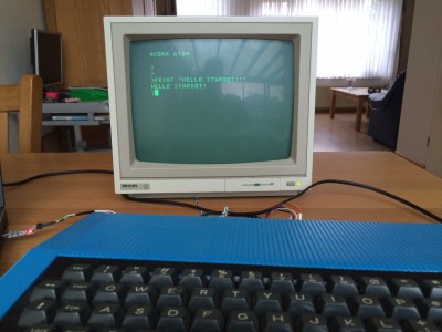
Testing your Atom
If you have done a nice job of soldering, do a visible check for short circuits. Also double check if there are no components installed in the wrong position (in many cases you will swap Vcc and Gnd with kills the component). If you are ready, connect a monitor to the main board and power the system on. If every thing went well, you'll see the text ACORN ATOM at your screen. If every thing is better then well, you'll also see + ATOMMC2 and a prompt.